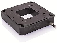
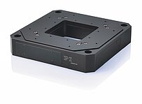
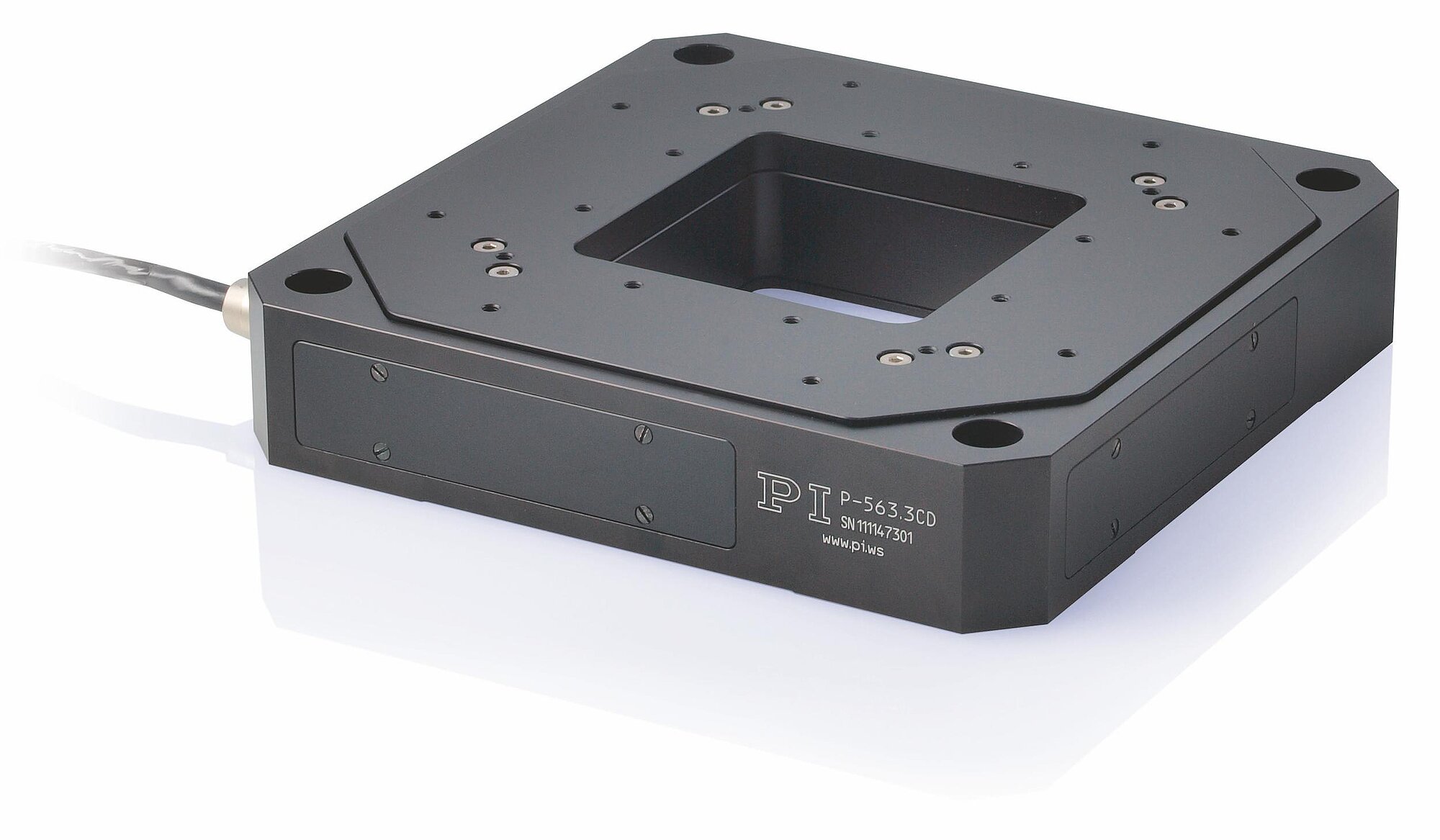
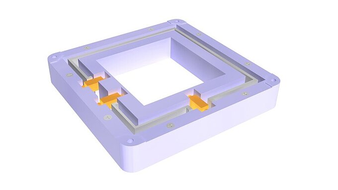
P-561.3CD
PIMars nanopositioning stage; 100 µm × 100 µm × 100 µm travel range (X × Y × Z), capacitive, indirect position measuring; D-sub 25W3 (m)


Application fields
Outstanding lifetime due to PICMA® piezo actuators
The PICMA® piezo actuators are all-ceramic insulated. This protects them against humidity and failure resulting from an increase in leakage current. PICMA® actuators offer an up to ten times longer lifetime than conventional polymer-insulated actuators. 100 billion cycles without a single failure are proven.
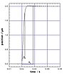
Subnanometer resolution with capacitive sensors
Capacitive sensors measure with subnanometer resolution without contacting. They guarantee excellent linearity of motion, long-term stability, and a bandwidth in the kHz range.
High guiding accuracy due to zero-play flexure guides
Flexure guides are free of maintenance, friction, and wear, and do not require lubrication. Their stiffness allows high load capacity and they are insensitive to shock and vibration. They work in a wide temperature range.
Automatic configuration and fast component exchange
Mechanical unit and controller can be can be combined as required and exchanged quickly. All servo and linearization parameters are stored in the ID chip of the mechanical unit's D-sub connector. The auto calibration function on the digital controller automatically uses this data every time the controller is switched on.
High tracking accuracy in the nanometer range due to parallel position measuring
All degrees of freedom are measured against a single fixed reference. Undesired crosstalk between axes can be actively compensated (active guiding) in real time (depending on the bandwidth). High tracking accuracy is achieved in the nanometer range even in dynamic operation.
| Motion | P-561.3CD | P-561.3CL | P-562.3CD | P-562.3CL | P-563.3CD | P-563.3CL | P-561.3DD | Tolerance |
|---|---|---|---|---|---|---|---|---|
| Active axes | X ǀ Y ǀ Z | X ǀ Y ǀ Z | X ǀ Y ǀ Z | X ǀ Y ǀ Z | X ǀ Y ǀ Z | X ǀ Y ǀ Z | X ǀ Y ǀ Z | |
| Travel range in X | 100 µm | 100 µm | 200 µm | 200 µm | 300 µm | 300 µm | 45 µm | |
| Travel range in Y | 100 µm | 100 µm | 200 µm | 200 µm | 300 µm | 300 µm | 45 µm | |
| Travel range in Z | 100 µm | 100 µm | 200 µm | 200 µm | 300 µm | 300 µm | 15 µm | |
| Travel range in X, open loop, at -20 to 120 V | 150 µm | 150 µm | 300 µm | 300 µm | 340 µm | 340 µm | 58 µm | +20 % / -0 % |
| Travel range in Y, open loop, at -20 to +120 V | 150 µm | 150 µm | 300 µm | 300 µm | 340 µm | 340 µm | 58 µm | +20 % / -0 % |
| Travel range in Z, open loop, at -20 to 120 V | 150 µm | 150 µm | 300 µm | 300 µm | 340 µm | 340 µm | 18 µm | +20 % / -0 % |
| Linearity error in X | 0.03 % | 0.03 % | 0.03 % | 0.03 % | 0.03 % | 0.03 % | 0.03 % | max. |
| Linearity error in Y | 0.03 % | 0.03 % | 0.03 % | 0.03 % | 0.03 % | 0.03 % | 0.03 % | max. |
| Linearity error in Z | 0.03 % | 0.03 % | 0.03 % | 0.03 % | 0.03 % | 0.03 % | 0.08 % | max. |
| Straightness error E_XZ | ± 30 nm | ± 30 nm | ± 50 nm | ± 50 nm | ± 50 nm | ± 50 nm | ± 20 nm | typ. |
| Straightness error E_YZ | ± 30 nm | ± 30 nm | ± 50 nm | ± 50 nm | ± 50 nm | ± 50 nm | ± 20 nm | typ. |
| Straightness error E_ZX (flatness) | ± 15 nm | ± 15 nm | ± 20 nm | ± 20 nm | ± 25 nm | ± 25 nm | ± 10 nm | typ. |
| Straightness error E_ZY (flatness) | ± 15 nm | ± 15 nm | ± 20 nm | ± 20 nm | ± 25 nm | ± 25 nm | ± 10 nm | typ. |
| Angular error E_AY (pitch) | ± 1 µrad | ± 1 µrad | ± 2 µrad | ± 2 µrad | ± 2 µrad | ± 2 µrad | ± 3 µrad | typ. |
| Angular error E_AZ | ± 15 µrad | ± 15 µrad | ± 20 µrad | ± 20 µrad | ± 25 µrad | ± 25 µrad | ± 3 µrad | typ. |
| Angular error E_BX (pitch) | ± 1 µrad | ± 1 µrad | ± 2 µrad | ± 2 µrad | ± 2 µrad | ± 2 µrad | ± 3 µrad | typ. |
| Angular error E_BZ | ± 15 µrad | ± 15 µrad | ± 20 µrad | ± 20 µrad | ± 25 µrad | ± 25 µrad | ± 3 µrad | typ. |
| Angular error E_CX (yaw) | ± 6 µrad | ± 6 µrad | ± 10 µrad | ± 10 µrad | ± 10 µrad | ± 10 µrad | ± 3 µrad | typ. |
| Angular error E_CY (yaw) | ± 6 µrad | ± 6 µrad | ± 10 µrad | ± 10 µrad | ± 10 µrad | ± 10 µrad | ± 3 µrad | typ. |
| Positioning | P-561.3CD | P-561.3CL | P-562.3CD | P-562.3CL | P-563.3CD | P-563.3CL | P-561.3DD | Tolerance |
| Unidirectional repeatability in X | ± 2 nm | ± 2 nm | ± 2 nm | ± 2 nm | ± 2 nm | ± 2 nm | ± 2 nm | typ. |
| Unidirectional repeatability in Y | ± 2 nm | ± 2 nm | ± 2 nm | ± 2 nm | ± 2 nm | ± 2 nm | ± 2 nm | typ. |
| Unidirectional repeatability in Z | ± 2 nm | ± 2 nm | ± 4 nm | ± 4 nm | ± 4 nm | ± 4 nm | ± 2 nm | typ. |
| Resolution in X, open loop | 0.2 nm | 0.2 nm | 0.4 nm | 0.4 nm | 0.5 nm | 0.5 nm | 0.1 nm | typ. |
| Resolution in Y, open loop | 0.2 nm | 0.2 nm | 0.4 nm | 0.4 nm | 0.5 nm | 0.5 nm | 0.1 nm | typ. |
| Resolution in Z, open loop | 0.2 nm | 0.2 nm | 0.4 nm | 0.4 nm | 0.5 nm | 0.5 nm | 0.1 nm | typ. |
| Integrated sensor | Capacitive, indirect position measuring | Capacitive, indirect position measuring | Capacitive, indirect position measuring | Capacitive, indirect position measuring | Capacitive, indirect position measuring | Capacitive, indirect position measuring | Capacitive, indirect position measuring | |
| System resolution in X | 0.8 nm | 0.8 nm | 1 nm | 1 nm | 2 nm | 2 nm | 0.2 nm | |
| System resolution in Y | 0.8 nm | 0.8 nm | 1 nm | 1 nm | 2 nm | 2 nm | 0.2 nm | |
| System resolution in Z | 0.8 nm | 0.8 nm | 1 nm | 1 nm | 2 nm | 2 nm | 0.2 nm | |
| Drive properties | P-561.3CD | P-561.3CL | P-562.3CD | P-562.3CL | P-563.3CD | P-563.3CL | P-561.3DD | Tolerance |
| Drive type | PICMA® | PICMA® | PICMA® | PICMA® | PICMA® | PICMA® | PICMA® | |
| Electrical capacitance in X | 5.2 µF | 5.2 µF | 7.4 µF | 7.4 µF | 7.4 µF | 7.4 µF | 38 µF | ±20 % |
| Electrical capacitance in Y | 5.2 µF | 5.2 µF | 7.4 µF | 7.4 µF | 7.4 µF | 7.4 µF | 38 µF | ±20 % |
| Electrical capacitance in Z | 10.4 µF | 10.4 µF | 14.8 µF | 14.8 µF | 14.8 µF | 14.8 µF | 6 µF | ±20 % |
| Mechanical properties | P-561.3CD | P-561.3CL | P-562.3CD | P-562.3CL | P-563.3CD | P-563.3CL | P-561.3DD | Tolerance |
| Resonant frequency in X, unloaded | 190 Hz | 190 Hz | 160 Hz | 160 Hz | 140 Hz | 140 Hz | 920 Hz | ±20 % |
| Resonant frequency in X, under load with 350 g | 150 Hz | 150 Hz | 125 Hz | 125 Hz | 93 Hz | 93 Hz | 640 Hz | ±20 % |
| Resonant frequency in Y, unloaded | 190 Hz | 190 Hz | 160 Hz | 160 Hz | 140 Hz | 140 Hz | 920 Hz | ±20 % |
| Resonant frequency in Y, under load with 350 g | 150 Hz | 150 Hz | 125 Hz | 125 Hz | 93 Hz | 93 Hz | 640 Hz | ±20 % |
| Resonant frequency in Z, unloaded | 380 Hz | 380 Hz | 315 Hz | 315 Hz | 250 Hz | 250 Hz | 1050 Hz | ±20 % |
| Resonant frequency in Z, under load with 350 g | 260 Hz | 260 Hz | 211 Hz | 211 Hz | 148 Hz | 148 Hz | 695 Hz | ±20 % |
| Permissible push force in X | 60 N | 60 N | 50 N | 50 N | 40 N | 40 N | 200 N | max. |
| Permissible push force in Y | 60 N | 60 N | 50 N | 50 N | 40 N | 40 N | 200 N | max. |
| Permissible push force in Z | 100 N | 100 N | 60 N | 60 N | 30 N | 30 N | 250 N | max. |
| Permissible pull force in X | 40 N | 40 N | 40 N | 40 N | 30 N | 30 N | 70 N | max. |
| Permissible pull force in Y | 40 N | 40 N | 40 N | 40 N | 30 N | 30 N | 70 N | max. |
| Permissible pull force in Z | 100 N | 100 N | 60 N | 60 N | 30 N | 30 N | 60 N | max. |
| Guide | Flexure guide with lever amplification | Flexure guide with lever amplification | Flexure guide with lever amplification | Flexure guide with lever amplification | Flexure guide with lever amplification | Flexure guide with lever amplification | Flexure guide with direct drive | |
| Overall mass | 1450 g | 1450 g | 1450 g | 1450 g | 1450 g | 1450 g | 1550 g | ±5 % |
| Material | Aluminum | Aluminum | Aluminum | Aluminum | Aluminum | Aluminum | Aluminum | |
| Resonant frequency in X, under load with 100 g | — | — | 145 Hz | 145 Hz | 120 Hz | 120 Hz | 860 Hz | ±20 % |
| Resonant frequency in Y, under load with 100 g | — | — | 145 Hz | 145 Hz | 120 Hz | 120 Hz | 860 Hz | ±20 % |
| Resonant frequency in Z, under load with 100 g | — | — | 275 Hz | 275 Hz | 215 Hz | 215 Hz | 950 Hz | ±20 % |
| Miscellaneous | P-561.3CD | P-561.3CL | P-562.3CD | P-562.3CL | P-563.3CD | P-563.3CL | P-561.3DD | Tolerance |
| Operating temperature range | -20 to 80 °C | -20 to 80 °C | -20 to 80 °C | -20 to 80 °C | -20 to 80 °C | -20 to 80 °C | -20 to 80 °C | |
| Connector | D-sub 25W3 (m) | LEMO LVPZT | D-sub 25W3 (m) | LEMO LVPZT | D-sub 25W3 (m) | LEMO LVPZT | D-sub 25W3 (m) | |
| Cable length | 1.5 m | 1.5 m | 1.5 m | 1.5 m | 1.5 m | 1.5 m | 1.5 m | +50 mm / -0 mm |
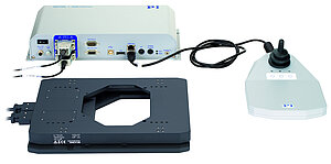
| Recommended controllers/drivers | E-503, E-505, E-621, E-713, E-727 | E-503, E-505, E-621, E-713, E-727 | E-503, E-505, E-621, E-713, E-727 | E-503, E-505, E-621, E-713, E-727 | E-503, E-505, E-621, E-713, E-727 | E-503, E-505, E-621, E-713, E-727 | E-503, E-505, E-621, E-713, E-727 |
Linearity error of P-561.3DD: With digital controller. Nonlinearity of direct drive positioners measured with analog controllers is typically up to 0.1 %.
Parallel kinematics only available for the X and Y axes (not in Z).
The resolution of the system is limited only by the noise of the amplifier and the measuring technology because PI piezo nanopositioning systems are free of friction.
Super Invar and titanium versions available.
Ask about customized versions.
At PI, technical data is specified at 22 ±3 °C. Unless otherwise stated, the values are for unloaded conditions. Some properties are interdependent. The designation "typ." indicates a statistical average for a property; it does not indicate a guaranteed value for every product supplied. During the final inspection of a product, only selected properties are analyzed, not all. Please note that some product characteristics may deteriorate with increasing operating time.
Unpacking and Packing P-5xx Positioners
P-561, P-562, P-563 PIMars XYZ Nanopositioning Systems
Ask for a free quote on quantities required, prices, and lead times or describe your desired modification.
PIMars nanopositioning stage; 100 µm × 100 µm × 100 µm travel range (X × Y × Z), capacitive, indirect position measuring; D-sub 25W3 (m)
PIMars nanopositioning stage; 100 µm × 100 µm × 100 µm travel range (X × Y × Z), capacitive, indirect position measuring; LEMO LVPZT
PIMars nanopositioning stage; 200 µm × 200 µm × 200 µm travel range (X × Y × Z), capacitive, indirect position measuring; D-sub 25W3 (m)
PIMars nanopositioning stage; 200 µm × 200 µm × 200 µm travel range (X × Y × Z), capacitive, indirect position measuring; LEMO LVPZT
PIMars nanopositioning stage; 300 µm × 300 µm × 300 µm travel range (X × Y × Z), capacitive, indirect position measuring; D-sub 25W3 (m)
PIMars nanopositioning stage; 300 µm × 300 µm × 300 µm travel range (X × Y × Z), capacitive, indirect position measuring; LEMO LVPZT
PIMars nanopositioning stage; 45 µm × 45 µm × 15 µm travel range (X × Y × Z); capacitive, indirect position measuring; D-sub 25W3 (m); direct drive
Quickly receive an answer to your question by email or phone from a local PI sales engineer.
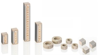
Highly reliable and extended lifetime through the patented manufacturing process for multilayer actuators.
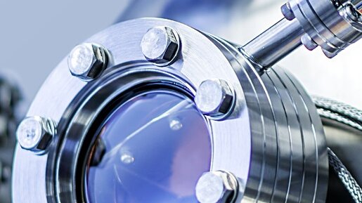
Careful handling, adequate premises: PI does not only have the necessary equipment for the qualification of materials, components and final products, but also has many years of experience with regard to HV und UHV positioning systems.
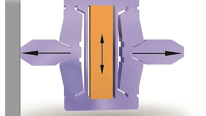
Flexure guides from PI have proven their worth in nanopositioning. They guide the piezo actuator and ensure a straight motion without tilting or lateral offset.

Digital technology opens up possibilities for improving performance in control engineering which do not exist with conventional analog technology.

Capacitive sensors are the metrology system of choice for the most demanding nanopositioning applications.
In a parallel-kinematic, multi-axis system, all actuators act directly on a single moving platform.