A DC motor with position measurement is called servo motor. The typical characteristics of DC servo motors are uniform, vibration-free operation, a large velocity range, and high torques at low velocity. To benefit in a best possible way from these properties, a motor controller with proportional, integral, and differential control (PID) and suitable filters is required. The servo motor has numerous advantages, such as good dynamics, fast addressing, high torques at low velocities, reduced heat generation, and low vibration.
DC servo motors require an operating voltage up to 12 VDC. The rotational velocity of the motor is directly proportional to the voltage; the prefix determines the direction. Repeatable positioning requires an additional measuring system.
Brushless DC Motor
PI increasingly uses electronically commuted, brushless DC motors, whereby optimized hollow shaft or torque motors achieve high torques. At the same time, the drive train can be made shorter for the same travel range as the drive shaft is located inside the motor.
ActiveDrive DC Motors
DC motor drives have numerous advantages, including good dynamic performance with a large control range, high torque at low revolutions, low heat dissipation, and low vibration at high position resolution. The cost of a high-performance linear amplifier, however, is generally higher than that for a stepper motor. The ActiveDrive system reduces this cost considerably by integrating a PWM (pulse width modulation) servo amplifier in the motor housing. The operating voltage of normally 24 V for ActiveDrive motors is supplied by a separate power supply included in the scope of delivery. The ActiveDrive concept provides several advantages:
Stepper Motor Drives
Contrary to DC motors, stepper motors only take up discrete positions in a revolution. As these steps have a constant distance, a position may be commanded using the number of steps without any need of a position sensor. Normally, there are 200 to 1000 full steps in each revolution. The actually achievable step width is determined by the stepper motor control, which electronically interpolates up to several hundred thousand microsteps in between the full steps depending on the version PI uses smoothly running 2-phase stepper motors. Stepper motors have a very long service life and, compared to DC motors, are especially suited for applications with reduced dynamics and in a vacuum. A mechanical damper on the motor shaft, which also serves as a handwheel, ensures running smoothness. To maintain a position, stepper motors without self-locking gearhead need to be energized continually. This may cause a position jitter between the steps and generate heat.
System Management Controller Technology for Controlled Stepper Motor Stages
The control technology of the System Management Controller (SMC) stepper motor controls guarantees particularly smooth running of the motors. The result is a very high position resolution, smooth feed, and a large dynamic range of velocity and acceleration. The efficiency of the System Management Controller is very high so that heating of the motors is avoided. System Management Controllers are based on a 32-bit processor with high-resolution amplifiers enabling a position resolution down to the nanometer range. In combination with high-precision mechanical systems, uniform feed velocities of less than 1 μm/s can be achieved. Instead of a linear acceleration profile, a sin2 profile can be chosen so that smooth acceleration and deceleration phases are possible. If stable long-term positioning is required, System Management Controller stepper motor controllers also evaluate position measurement systems and control precisely. Processing of an analog 1 V peak-to-peak value allows setting the position very accurately and infinitely without limitation by bit-depending digital transformation.
System Management Controllers are available in different versions, from a one-channel compact unit to multi-axis control in a 19" housing.
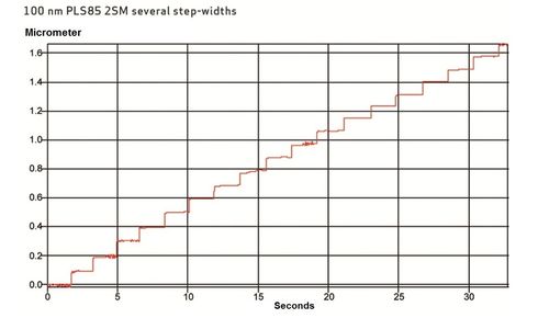
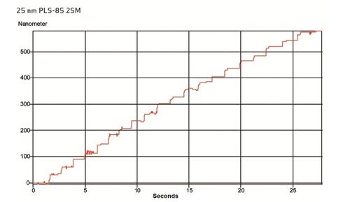
Fig. 1 shows 100 nm steps of a PLS-85 linear stage with two-phase stepper motor without additional position feedback. The stage carries out these steps with great precision. When commanding 25 nm steps (see Fig. 2), there are more variations in the individual steps. On average, these deviations are only ±5 nm.
Position Control
The position behavior for small steps can be further improved by using a position control, in particular, if the analog output signal of a high-resolution sensor is used for processing. System Management Controllers can process sensor resolutions down to 2 nm, position resolution then only depends on the sensor. However, the environmental effects should not be neglected: variations in ambient temperature of only 0.01 °C already cause thermally induced expansion of the stage by approx. 10 nm. If required, ultra-precision stages or specific developments, such as stages with a granite base and corresponding high-resolution linear encoders, are used.
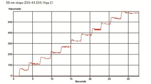
Fig. 3 shows the measured minimum incremental motion of an LS-110 stage with linear encoder. The 50 nm resolution can be clearly seen with precisely separated steps. Even changes in load do not affect this accuracy.
Velocity Control
One decisive parameter for selecting a positioning system is velocity. More often than not this relates to the maximum achievable velocity, but some applications require a particularly slow and even feed motion. This is a major challenge for both stepper motors and DC motors. The velocity control of System Management Controllers guarantees an excellent stability of the stage velocity in the range of << 1 µm/s.
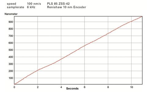
Fig. 4 shows the measuring results of a PLS-85 stage with integrated linear encoder with 10 nm resolution. The velocity was set to 100 nm/s, which equates to a feed of 360 µm/h or approx. 10 mm/d. The motion is very even. The individual steps shown here are due to the interferometer resolution of 5 nm.
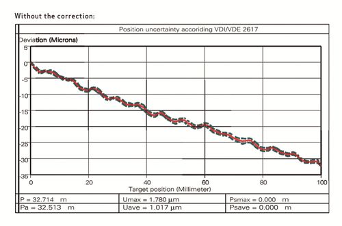
The quality of the guides and the drive train normally limits the positioning accuracy that can be achieved. A nonlinearity of the spindle pitch, for example, causes a deviation from the commanded position. In some applications it is important to improve the absolute positioning accuracy while bidirectional repeatability is less relevant. The error correction in the System Management Controller saves the measured deviation and then corrects the target position correspondingly.
Fig. 5 shows the deviation in position of 32 µm between target and actual position of an LS-180 over the travel range of 100 mm. The measurement includes both directions of motion; the average bidirectional repeatability is 1.78 µm.
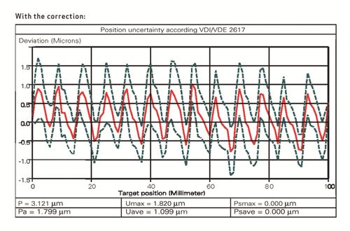
The result is shown in Fig. 6: the deviation is considerably smaller, only about ±1.5 µm. Repeatability can be improved further by means of position control.
Ask an engineer!
Quickly receive an answer to your question by email or phone from a local PI sales engineer.
Downloads
Rotating Electric Motors for Precision Positioning
An application-related comparison of different motor types
Performance of Stepper Motor Axes
Optimization of Precision, Stability, and Repeatability
