Active Alignment
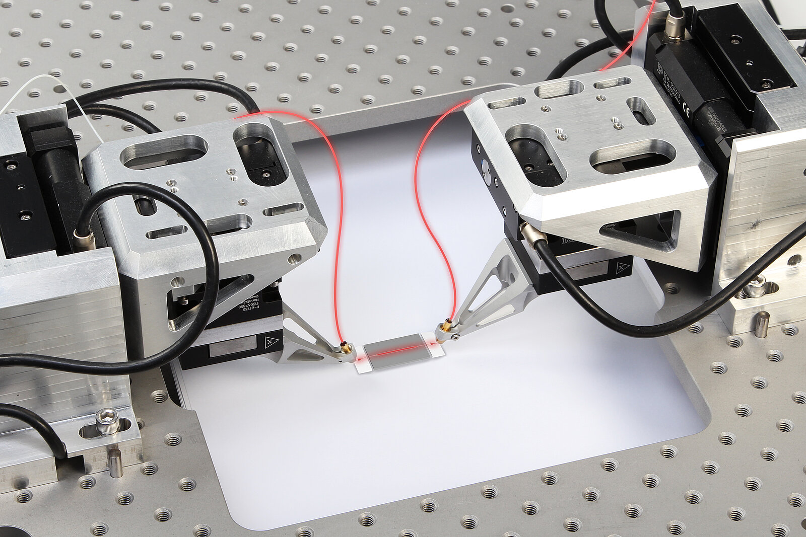
New needs to align devices down to nanoscale accuracy are arising in many manufacturing fields. Optical components such as the lenses in cameras, or the CCD chip itself, need to be positioned with ever more precision and economic efficiency. In silicon photonics (SiP), tiny devices need to be aligned for testing and packaging, starting at the wafer level. The common theme: multiple channels, multiple elements, multiple interacting inputs and outputs, across multiple degrees of freedom, all need to be aligned and optimized multiple times in the manufacturing process.
Fast Multichannel Photonics Alignment (FMPA) Technology
PI’s Fast Multichannel Photonics Alignment (FMPA) technology is a set of firmware-level commands built into its highest-performance digital nanopositioning and hexapod controllers. These commands allow fast coupling optimization between photonic and other optical devices and assemblies, including optimization across multiple degrees-of-freedom, inputs and outputs, elements and channels. Importantly, these optimizations can often be performed in parallel, i.e. simultaneously, even if the individual optimizations interact. This can yield vast reductions in assembly-time and cost-reductions of 99% are routinely seen.
Serial versus Parallel Alignments
For example, in the short waveguides increasingly utilized in silicon photonics devices, the input and output couplings can steer each other. As one side is optimized, the other shifts slightly and needs re-optimization. Formerly, this necessitated a time-consuming, serial sequence of back-and-forth adjustments of the input, then the output, repeating until a global consensus alignment was eventually achieved. Similarly, when optimizing an angle, the transverse alignment would be impacted and would conventionally need to be re-optimized, again in a time-consuming serial loop.
But with FMPA, these interacting alignments can often be optimized simultaneously, in parallel. This allows a global consensus alignment to be achieved in one go. Tracking and continuous optimization of all the alignments is also possible in many circumstances, allowing compensation of drift, curing stresses, and so on.
The results are much higher production throughput and often dramatically lower costs. As devices become more complex and precise, and as their production and test requirements grow more demanding, this parallelism is increasingly critical to process economics.
Different Alignment Processes
There are two types of processes: areal scans intended to localize a peak of some figure of merit (such as optical power, Modulation Transfer Function (MTF), modal purity,...) within a defined region, and gradient searches intended to efficiently optimize one or more such couplings at once (and optionally track them to mitigate drift processes, disturbances, etc.).
Gradient Searches
Gradient searches perform a small circular dither motion of one device versus the other, which modulates the coupling. The amount of modulation of the figure-of-merit being optimized is a measure of the local gradient of the coupling. The modulation falls to zero at optimum.
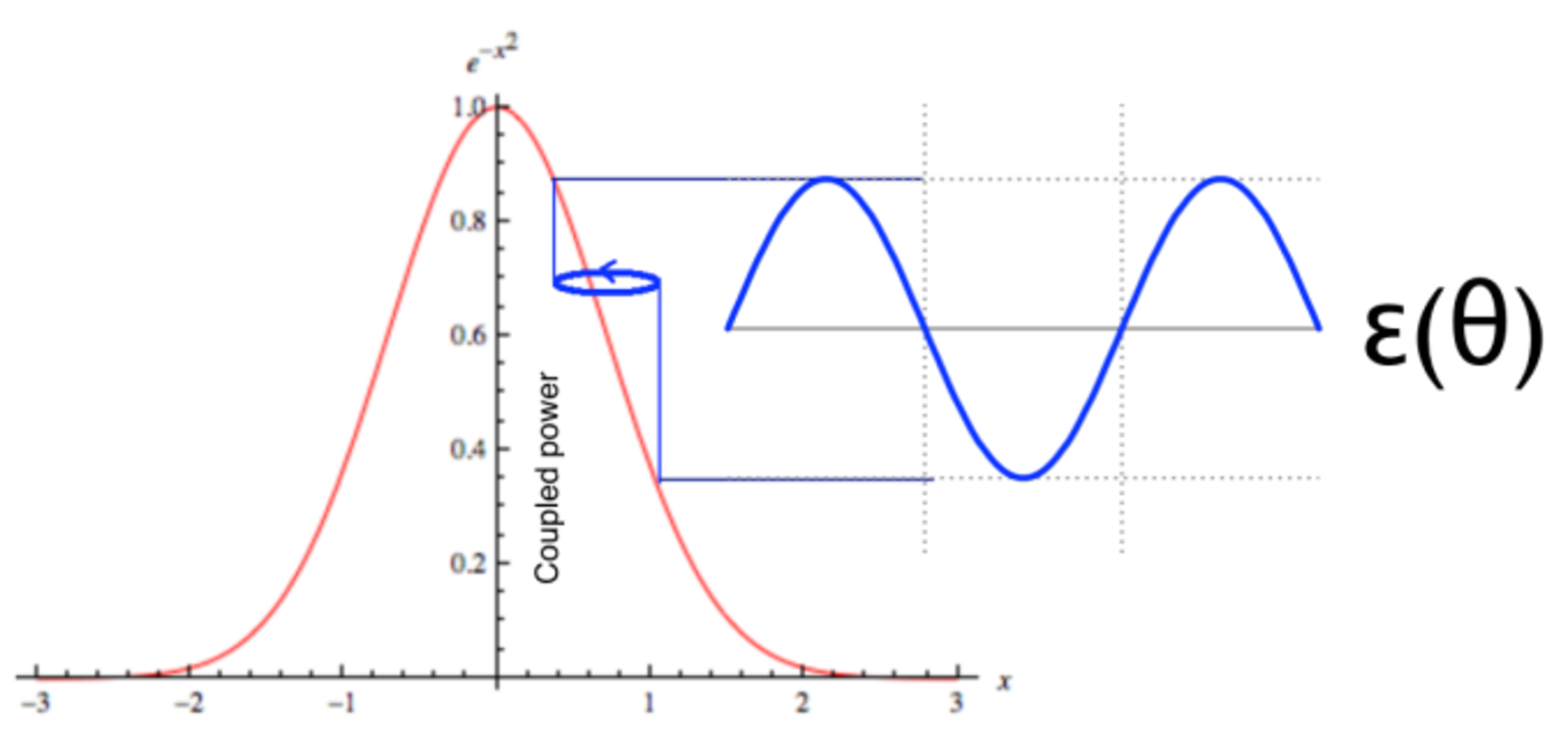
|ε(θ)|=∇I=(Imin-Imax)/Imin
Equation 1: The observed gradient serves as a measure of alignment error.
From the observed modulation the controller can mathematically deduce the local gradient via a very simple calculation such as Equation 1. Note that the gradient ∇I falls to zero at optimum.
Any axes in an FMPA system can perform any of these types of alignments (subject to the physical capabilities of the axes, of course).
Gradient searches are most familiar from transverse optimization but they can also be performed (for example) in a single linear axis, which is ideal for localizing the beam waist in a lensed coupling, or in a gimbaling fashion to optimize an angular orientation. These are highly general-purpose algorithms suitable for all kinds of optimizations, including bulk optic, cavity, and pinhole alignments.
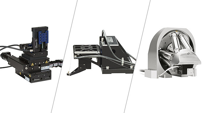
In general, a unique feature of FMPA is that different, even interacting gradient searches can be performed in parallel. Transverse optimizations tend to be the most sensitive and also the most affected by other alignments. So, transverse routines tend to be relegated to high-speed, high-resolution piezoelectric stages such as the >> P-616 NanoCube. The high speed and continuous tracking capability of the NanoCube allows transverse optimization to be maintained during Z and angular optimizations that would ordinarily require the time-consuming, looping sequential approach.
Areal Scans
Scanning an area to determine the approximate location of the highest coupling peak is useful for a variety of tasks:
- First-light seeking.
- Profiling for dimensional characterization of a coupling. This can be an important process-control step.
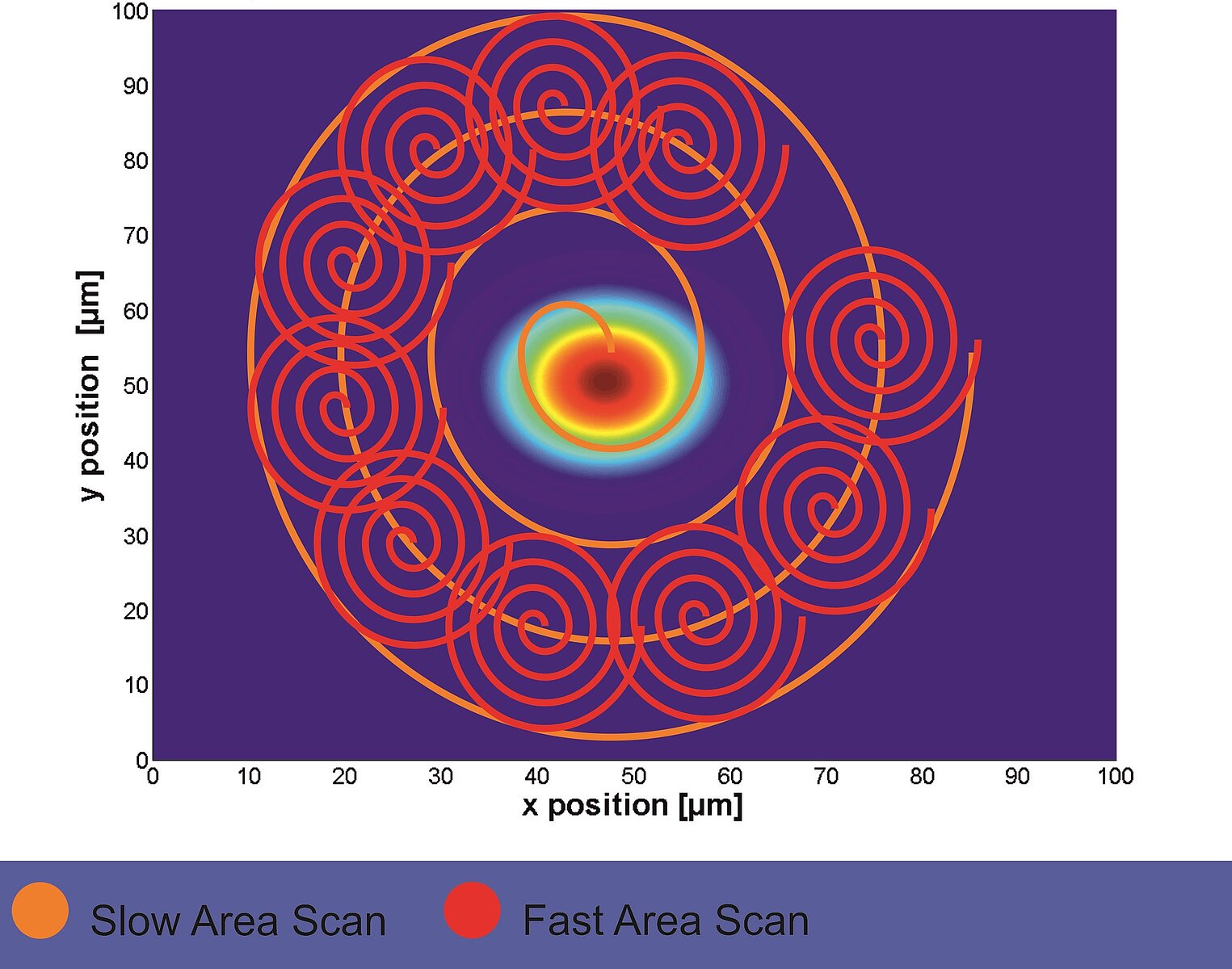
- Localizing the main mode of a coupling for subsequent optimization by a gradient search. This hybrid approach helps prevent locking-onto a local maximum and is very powerful.
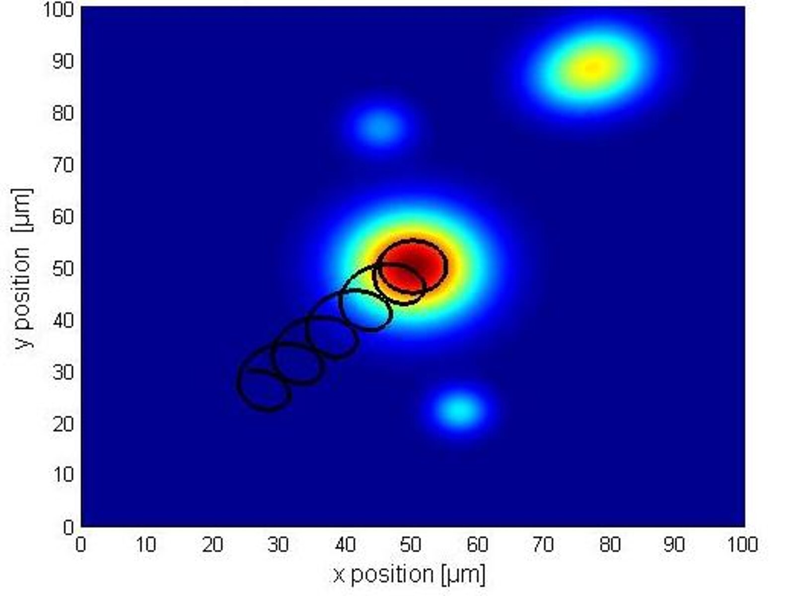
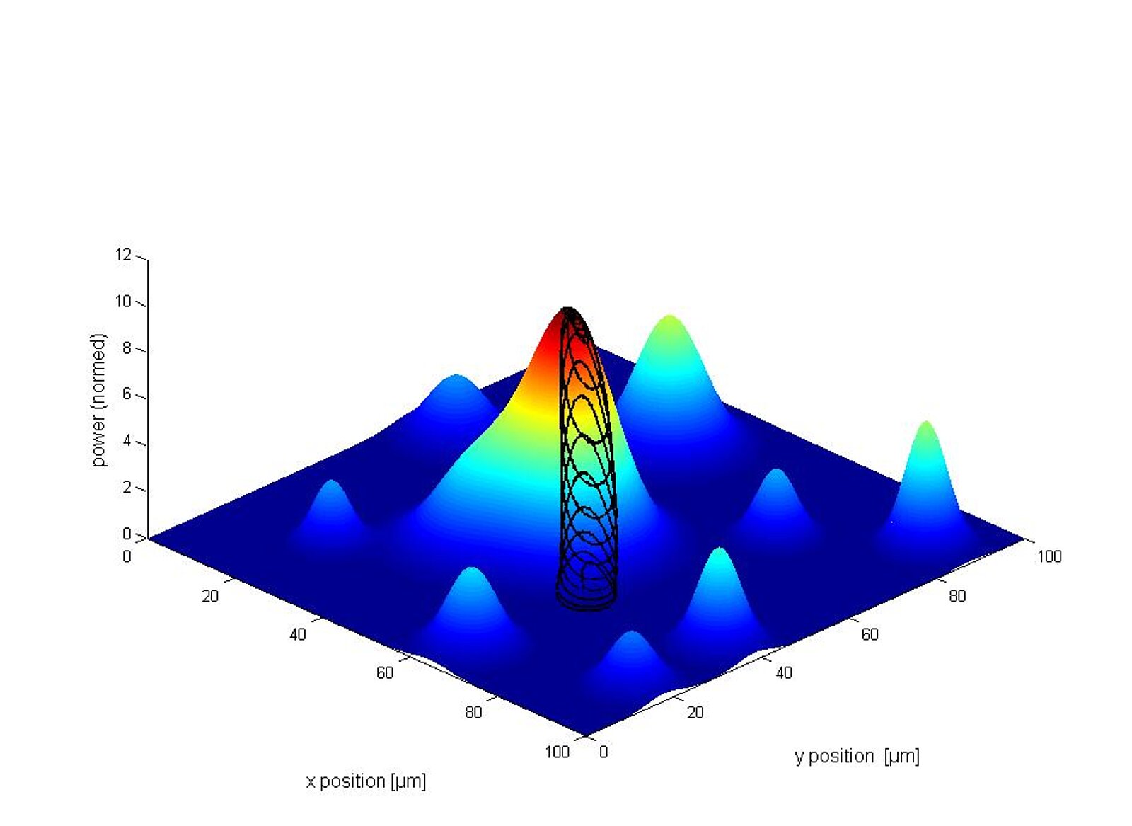
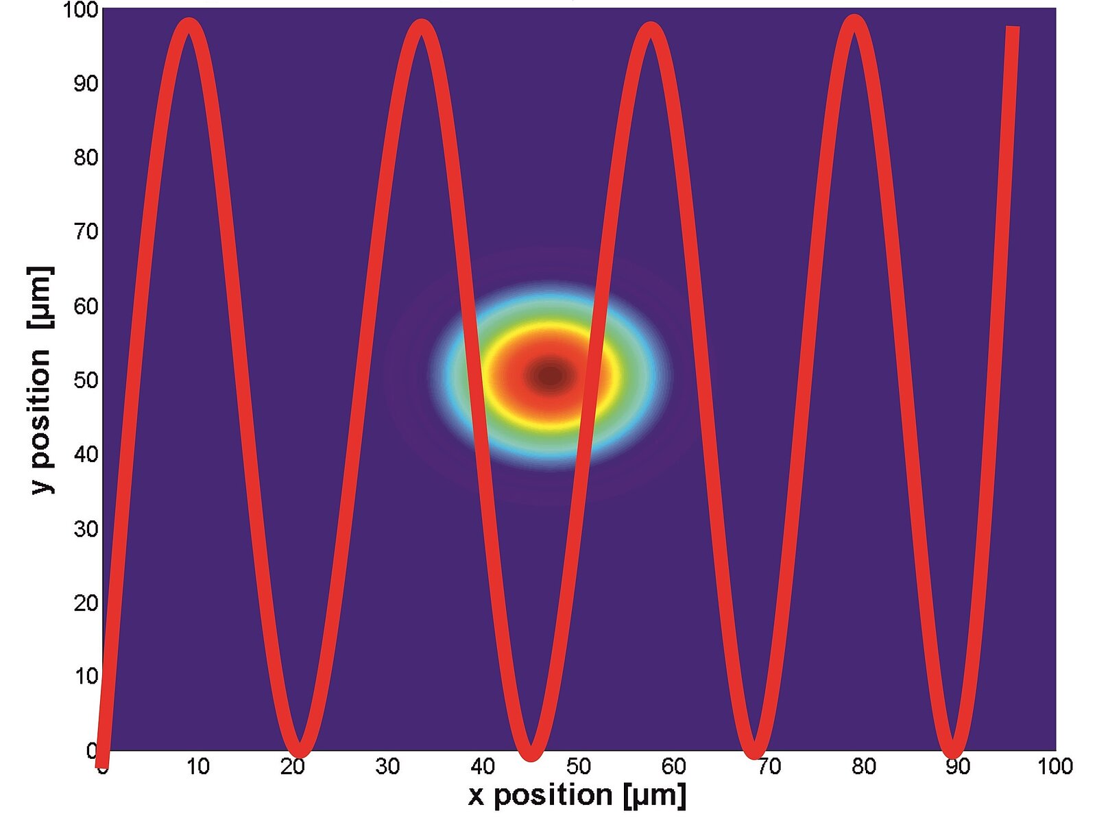
Uniquely, FMPA’s areal scan options include single-frequency sinusoid and spiral scans. These are much faster than traditional raster or serpentine scans since they are truly continuous and avoid the settling requirements of the stop-and-start motions used in the traditional scans, and the frequency can be selected to avoid exciting structural resonances. A constant-velocity spiral scan may also be selected, allowing data to be acquired with constant density across the spiral.
Optimizing the Optical Power Transmission
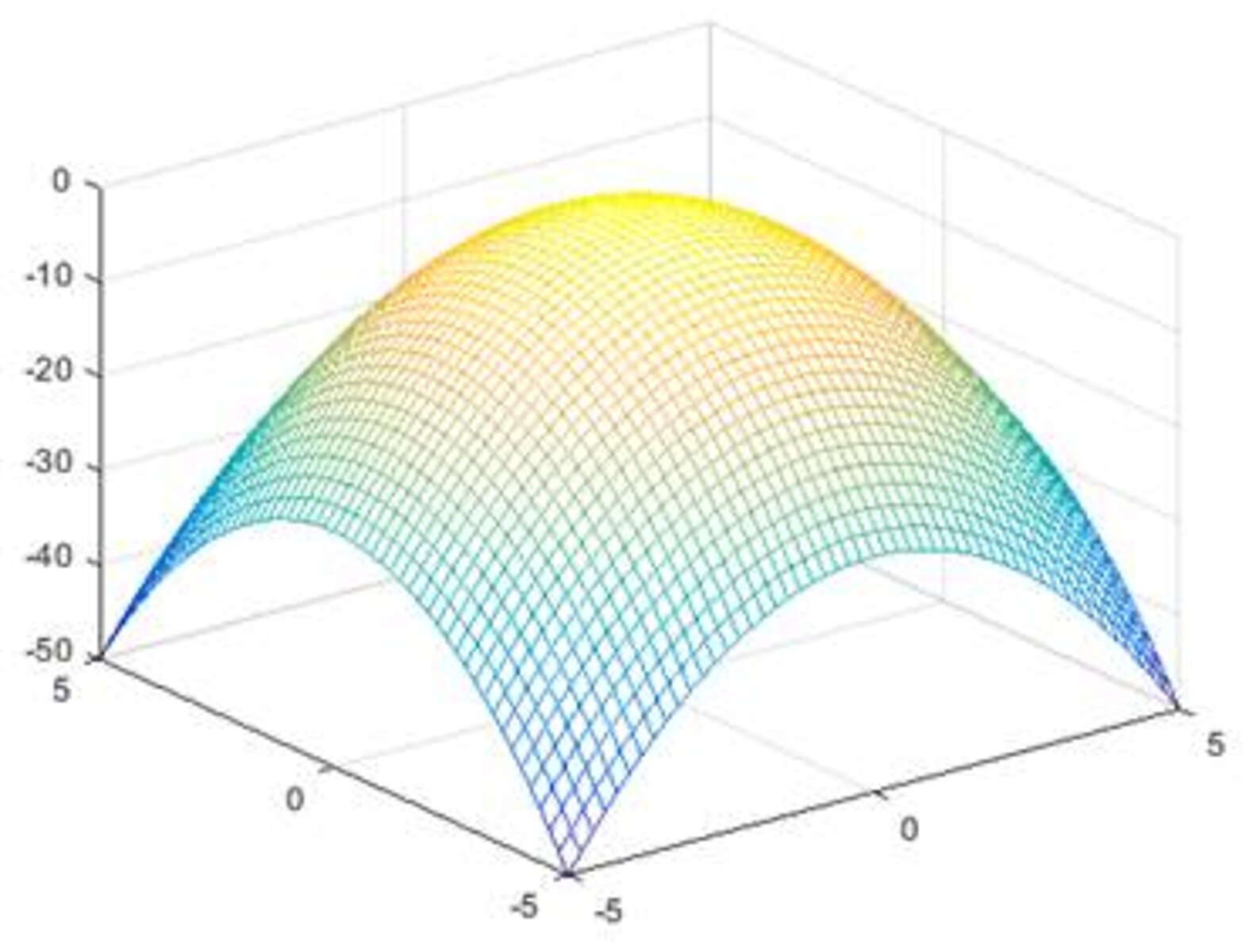
For some applications, the goal is to optimize the optical power transmission between elements. For example, in most Silicon Photonics (SiP) manufacturing steps, light from a fiber must be efficiently coupled into a silicon substrate or vice versa; the figure-of-merit in this case is optical power, and the metrology is an optical power meter. The coupling profile is very narrow-shaped which results in an equally narrow peak of power distribution. The high speeds demanded by today’s SiP production economics necessitate a meter of unusual speed, dynamic range and responsiveness.

Logarithmic Scaling of the Output Signal
Using a logarithmic response provides a much larger dynamic range for optical power metrology than a linear response. This is especially important for capture of small signals, e.g. when far from optimum alignment.
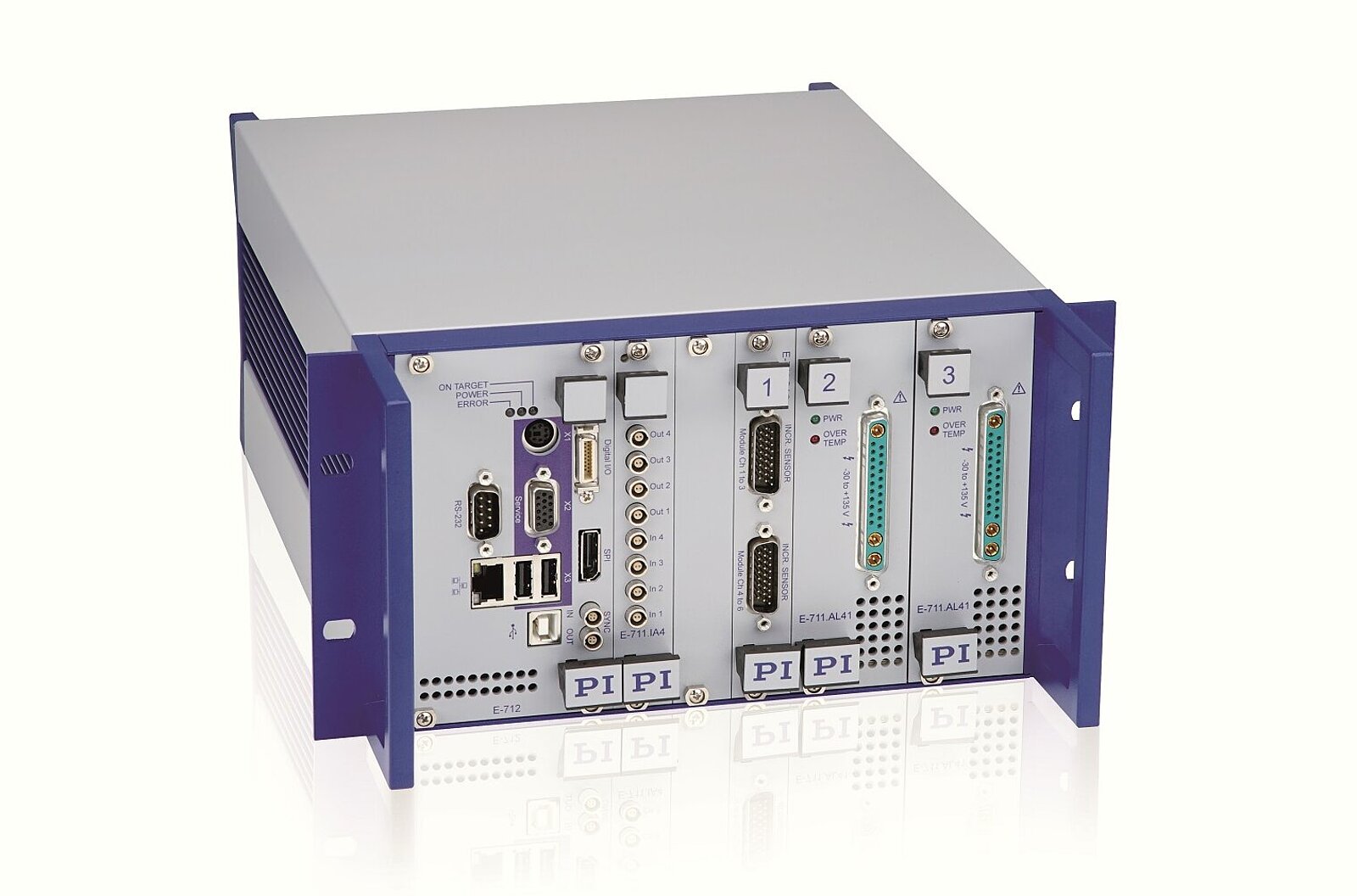
The fast alignment routines in PI’s controllers, such as E-712, preferably use a logarithmic power signal. The logarithmic response flattens the steep sides of the typically Gaussian-like coupling profile, allowing a smoother approach to maximum with less risk of overshoot.
Calculation of Optical Power
To obtain real power values it is necessary to convert the logarithmic signal. PI’s F-712 fast alignment systems, namely the E-712 controllers, provide an automatic conversion to power via software command.
To accurately compare these real power values with other measurement results, we recommend using a calibrated power meter, such as PI’s F-712.PM1.
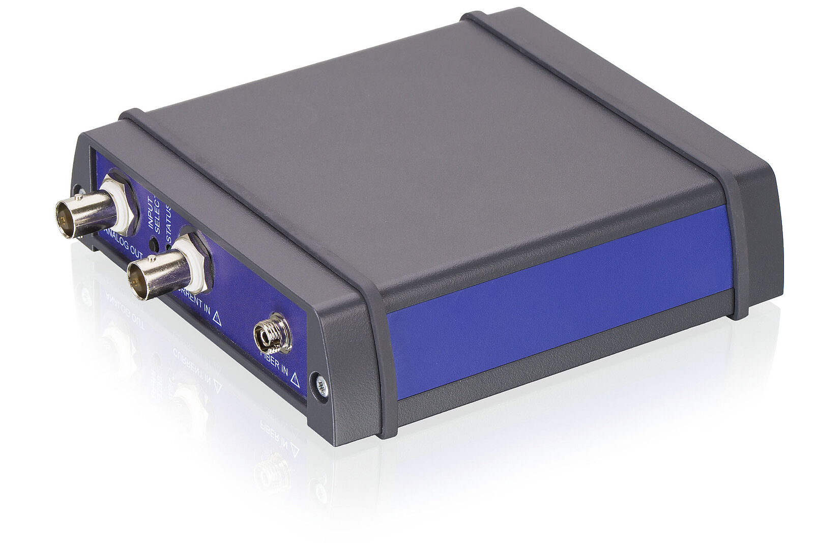
Using the F-712.PM1 Power Meter with F-712 High-Precision Fast Alignment Systems
The versatility of F-712 Fast Alignment Systems is enhanced by using the F-712.PM1 Optical Power Meter for power metrology in both the visible and infrared range.
The device also has a current input. For example, a photodiode can be connected to this input and the diode current converted into a logarithmic voltage signal. This can be used to quickly determine the optical signal strength, e.g. to check the function of individual components in a setup or to carry out a manual rough adjustment.
Independently of the source, the output signal is an analog, logarithmic voltage signal. This allows to take advantage of logarithmic scaling and measure optical power accurately over a wide range of input powers.
A simple software command inside the E-712 controller allows an automatic conversion of the logarithmic response signal to power.