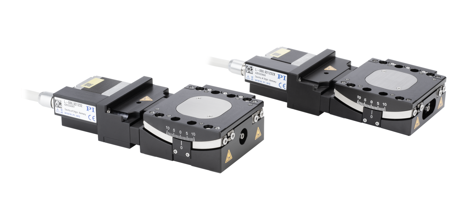
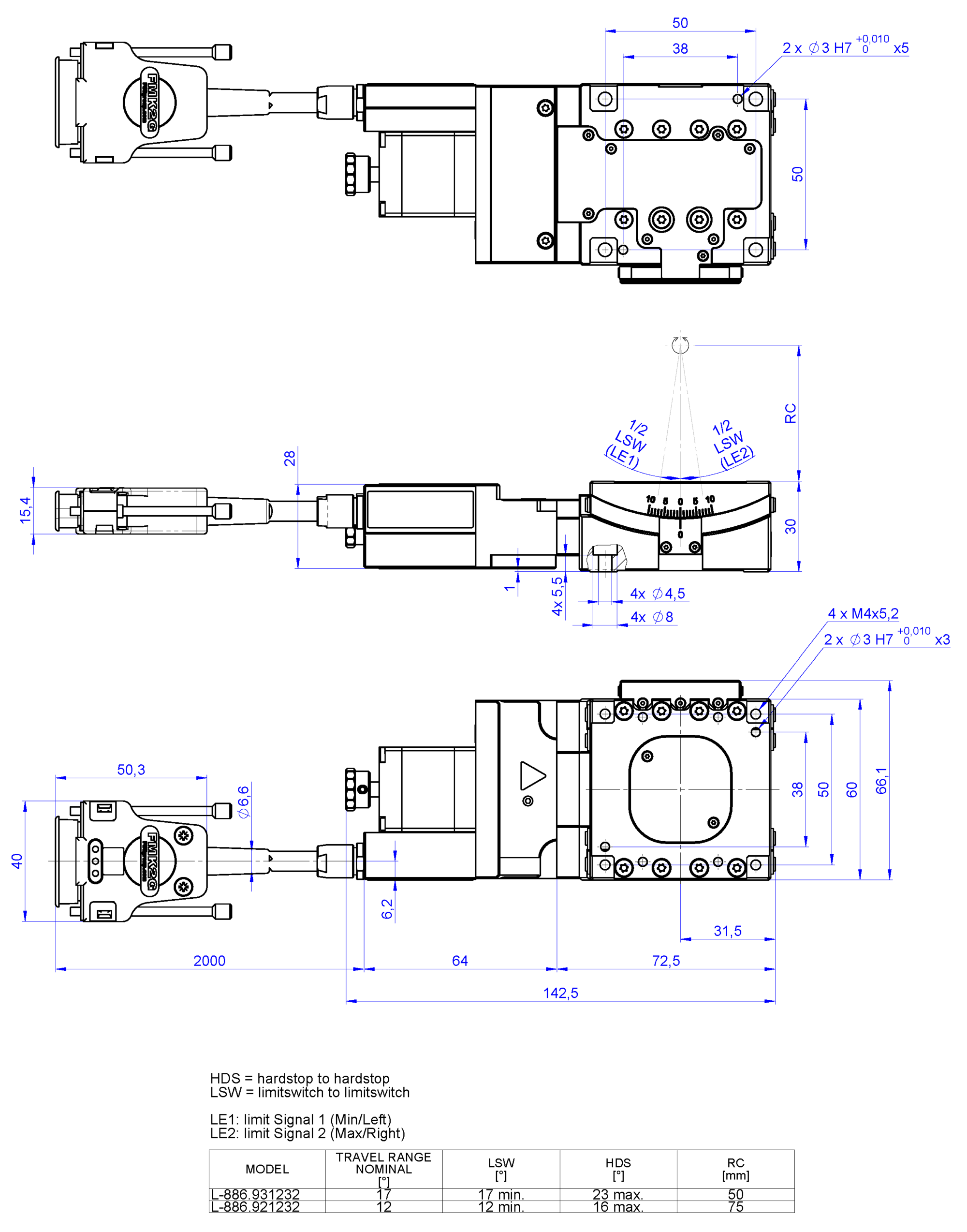
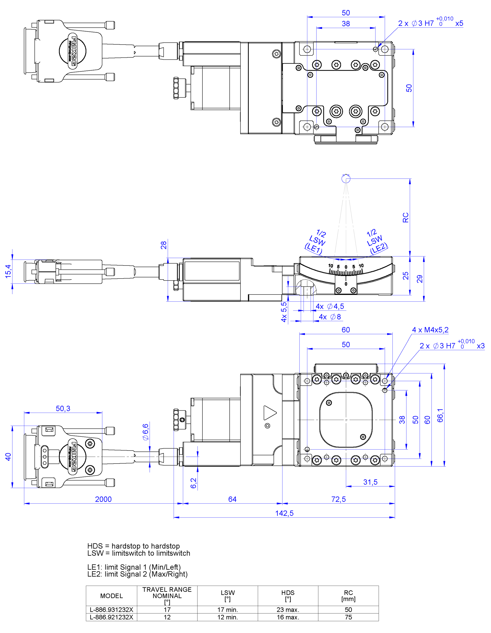
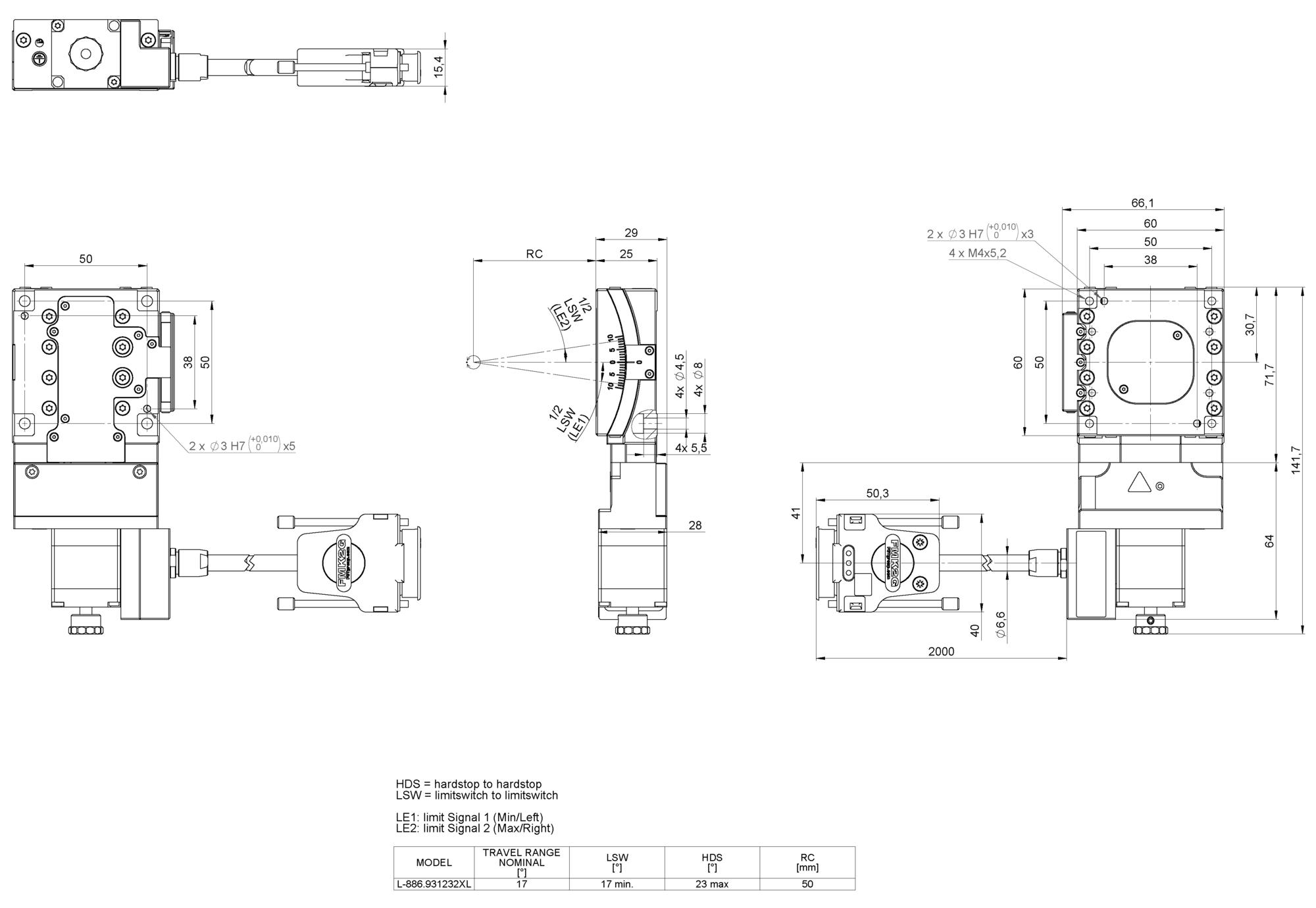
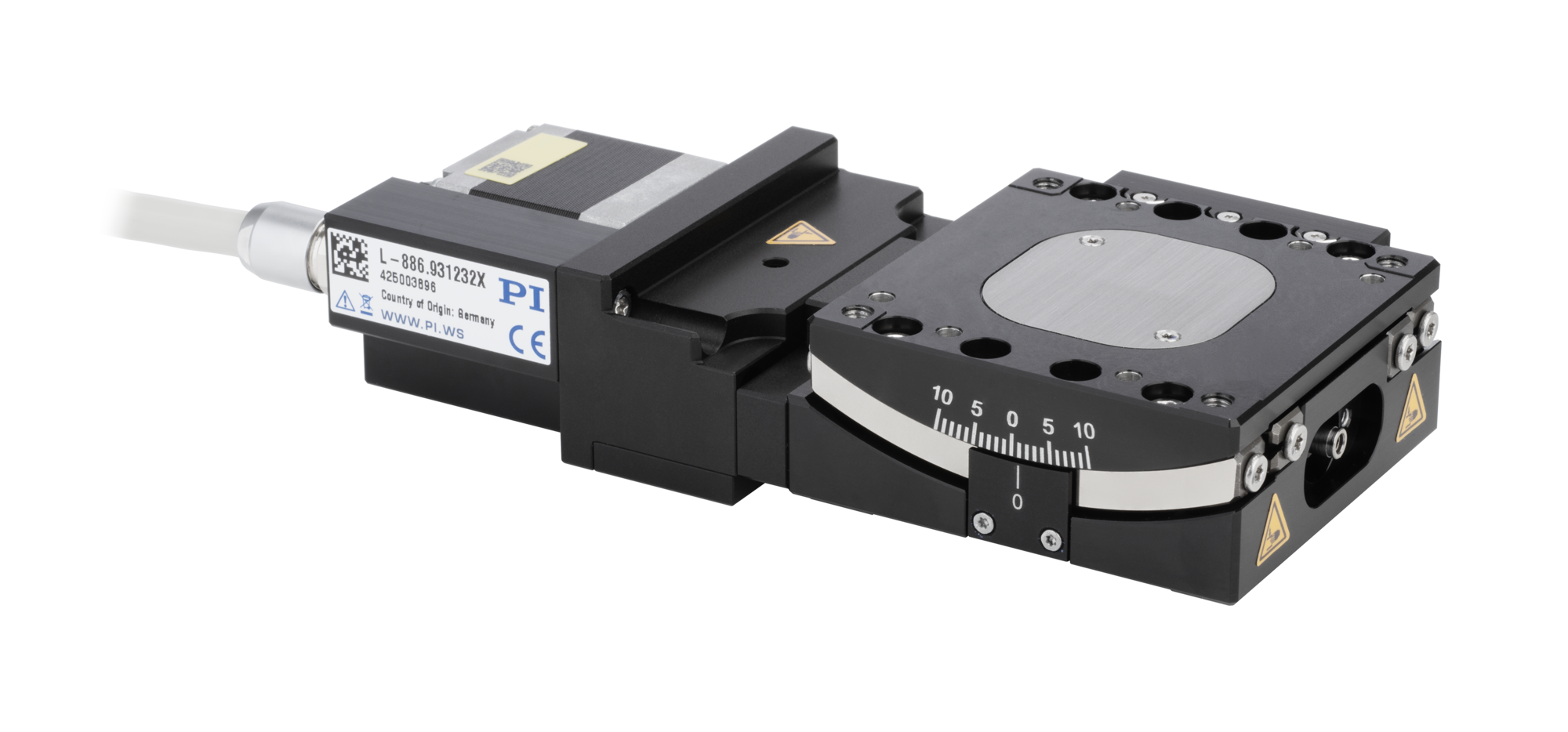
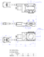
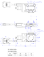
Goniometer with flat contact surface; 2-phase stepper motor; 12° rotational angle; 35 N payload; 10 °/s maximum angular velocity; ball screw; incremental linear encoder, 0.8305 µrad sensor resolution, rotational, A/B quadrature, RS-422; magnetic limit switches

L-886 Compact and Versatile Goniometer
High-Performance and Cost-Efficient
- Compact, stackable design with high flexibility: Thanks to its compact design and the ability to combine two goniometers with identical centers of rotation, the L-886 offers maximum flexibility for precise multichannel photonics alignment applications.
- Cost-effective complete solution for demanding applications: Unlike comparable solutions, the system offers an attractively priced alternative while meeting requirements such as 24/7 operation, large formats, and industrial operating conditions.
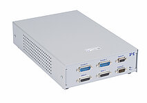
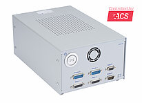
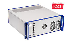
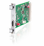
- Enhanced system compatibility and modern control integration: The system supports modern communication standards such as EtherCAT (e.g., with ACS controls) and can therefore easily be integrated into existing automated production environments.


The L-886 is an accurate, cost-effective goniometer stage. It is based on a stepper motor combined with a linear measurement system for high accuracy. The L-886 is designed for cost-conscious applications including micro assembly, component alignment, electronics manufacturing, and inspection.
Cost-effective solution, specifically designed for rapid alignment in multichannel photonics
Compact, precise, and fast
Application and use cases
Industrial automation applications:
Micro component placement
Alignment applications
Optical part alignment
Technology
The L-886 spindle-driven goniometer stages are ideally suited for industrial applications requiring high performance in a compact design. Their high performance is powered by high-resolution stepper motors, high-precision crossed roller guides, and precision linear encoders.
High-resolution 2-phase motors offer performance comparable to that of 5-phase stepper motors - but without the need for expensive drive electronics. Additional linear encoders provide high repeatability during operation.
Installation and operation
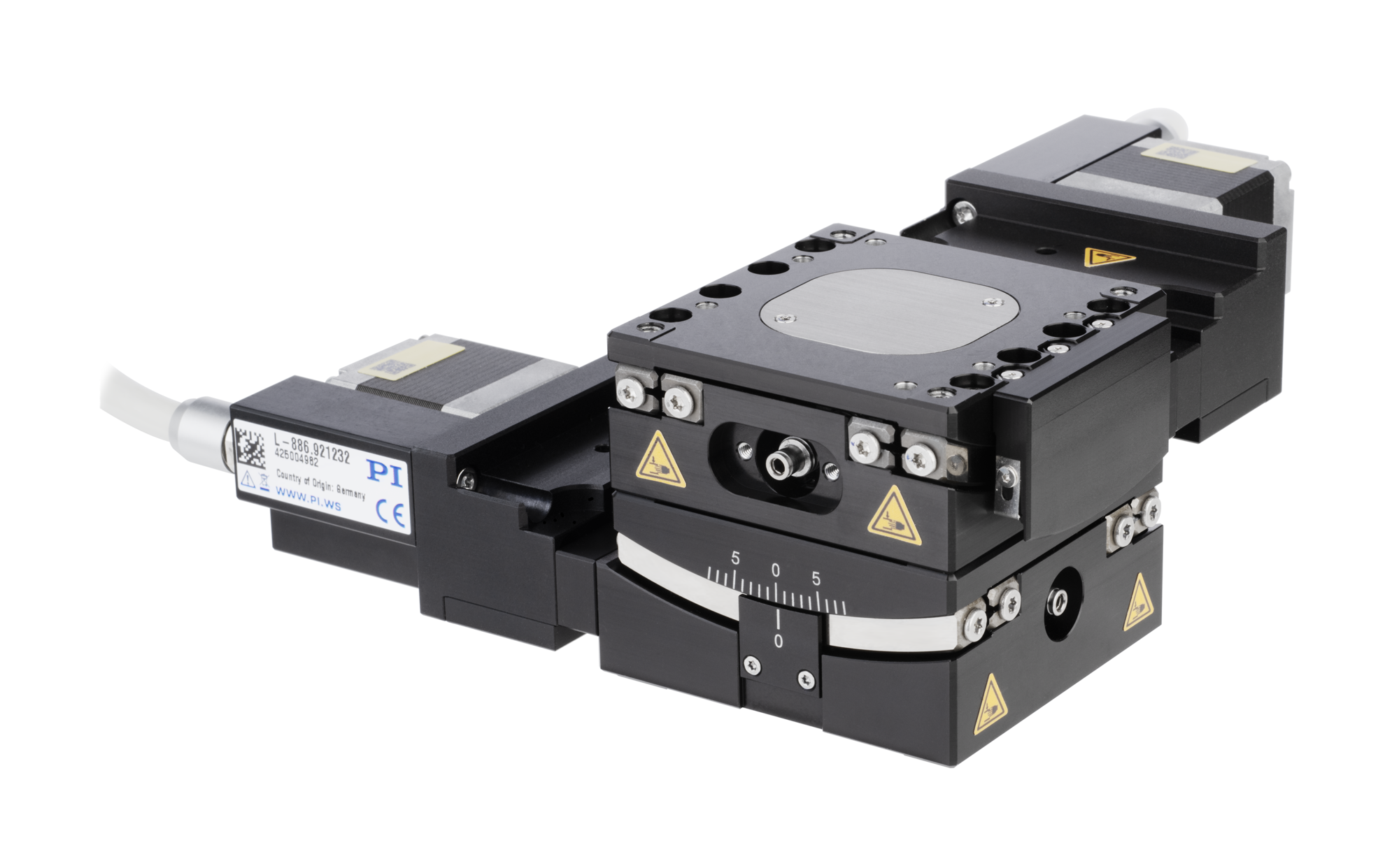
The goniometers can be mounted onto L-836 linear stages. The L-886 models are stackable for 2-axis motion. If an L‑886.931232X is mounted onto an L‑886.921232[X], the models will have a common center of rotation.
Specifications
Specifications
Positioning | Unit | Tolerance | L-886.921232 | L-886.921232X | L-886.931232 | L-886.931232X | L-886.931232XL |
|---|---|---|---|---|---|---|---|
Minimum incremental motion | μrad | typ. | 5 | 5 | 5 | 5 | 5 |
Bidirectional repeatability | μrad | typ. | 35 | 35 | 35 | 35 | 35 |
Reference switch |
|
| Hall effect, N/C contact, 5 V, NPN | Hall effect, N/C contact, 5 V, NPN | Hall effect, N/C contact, 5 V, NPN | Hall effect, N/C contact, 5 V, NPN | Hall effect, N/C contact, 5 V, NPN |
Limit switch |
|
| Hall effect, N/C contact, 5 V, NPN | Hall effect, N/C contact, 5 V, NPN | Hall effect, N/C contact, 5 V, NPN | Hall effect, N/C contact, 5 V, NPN | Hall effect, N/C contact, 5 V, NPN |
Integrated sensor |
|
| Incremental linear encoder | Incremental linear encoder | Incremental linear encoder | Incremental linear encoder | Incremental linear encoder |
Sensor signal |
|
| A/B quadrature, RS-422 | A/B quadrature, RS-422 | A/B quadrature, RS-422 | A/B quadrature, RS-422 | A/B quadrature, RS-422 |
Sensor resolution, rotational | μrad |
| 0.8305 | 0.8305 | 1.122 | 1.122 | 1.122 |
Drive properties | Unit | Tolerance | L-886.921232 | L-886.921232X | L-886.931232 | L-886.931232X | L-886.931232XL |
|---|---|---|---|---|---|---|---|
Drive type |
|
| 2-phase stepper motor | 2-phase stepper motor | 2-phase stepper motor | 2-phase stepper motor | 2-phase stepper motor |
Nominal voltage | V |
| 24 | 24 | 24 | 24 | 24 |
Peak current per phase, RMS | A | typ. | 1.5 | 1.5 | 1.5 | 1.5 | 1.5 |
Maximum power consumption | W |
| 8 | 8 | 8 | 8 | 8 |
Motor resolution | Full steps/rev. |
| 200 | 200 | 200 | 200 | 200 |
Phase resistance | Ω | typ. | 1.18 | 1.18 | 1.18 | 1.18 | 1.18 |
Phase inductance | mH |
| 0.96 | 0.96 | 0.96 | 0.96 | 0.96 |
Mechanical properties | Unit | Tolerance | L-886.921232 | L-886.921232X | L-886.931232 | L-886.931232X | L-886.931232XL |
|---|---|---|---|---|---|---|---|
Permissible push force in Z | N | max. | 35 | 35 | 35 | 35 | 35 |
Drive torque | Nm |
| 2.6 | 2.6 | 1.7 | 1.7 | 1.7 |
Holding torque, passive | Nm |
| 0.8 | 0.8 | 0.55 | 0.55 | 0.55 |
Distance of center of rotation to platform surface | mm | ±0.015 mm | 75 | 75 | 50 | 50 | 50 |
Drive screw type |
|
| Ball screw | Ball screw | Ball screw | Ball screw | Ball screw |
Spindle pitch | mm |
| 1 | 1 | 1 | 1 | 1 |
Guide |
|
| Crossed roller guide | Crossed roller guide | Crossed roller guide | Crossed roller guide | Crossed roller guide |
Material |
|
| Aluminum, black anodized; stainless steel | Aluminum, black anodized; stainless steel | Aluminum, black anodized; stainless steel | Aluminum, black anodized; stainless steel | Aluminum, black anodized; stainless steel |
Overall mass | g |
| 730 | 710 | 730 | 710 | 710 |
Mass without cables | g |
| 530 | 500 | 530 | 500 | 500 |
Miscellaneous | Unit | Tolerance | L-886.921232 | L-886.921232X | L-886.931232 | L-886.931232X | L-886.931232XL |
|---|---|---|---|---|---|---|---|
Operating temperature range | °C |
| 5 to 40 | 5 to 40 | 5 to 40 | 5 to 40 | 5 to 40 |
Connector |
|
| HD D-sub 26 (m) | HD D-sub 26 (m) | HD D-sub 26 (m) | HD D-sub 26 (m) | HD D-sub 26 (m) |
Cable exit |
|
| straight, to the rear | straight, to the rear | straight, to the rear | straight, to the rear | angled, 90°, to the left |
Recommended controllers/drivers |
|
| C-663, G-901, G-910, modular ACS controller | C-663, G-901, G-910, modular ACS controller | C-663, G-901, G-910, modular ACS controller | C-663, G-901, G-910, modular ACS controller | C-663, G-901, G-910, modular ACS controller |
At PI, technical data is specified at 22 ±3 °C. Unless otherwise stated, the values are for unloaded conditions. Some properties are interdependent. The designation "typ." indicates a statistical average for a property; it does not indicate a guaranteed value for every product supplied. During the final inspection of a product, only selected properties are analyzed, not all. Please note that some product characteristics may deteriorate with increasing operating time.
Downloads
Datasheet
Documentation
User Manual L886UM0001
L-886 Goniometer Stage
3D Models
L-886 3D Model
Ask for a free quote on quantities required, prices, and lead times or describe your desired modification.
Goniometer for stacked systems; 2-phase stepper motor; 12° rotational angle; 35 N payload; 10 °/s maximum angular velocity; ball screw; incremental linear encoder, 0.8305 µrad sensor resolution, rotational, A/B quadrature, RS-422; magnetic limit switches

Goniometer with flat contact surface; 2-phase stepper motor; 17° rotational angle; 35 N payload; 10 °/s maximum angular velocity; ball screw; incremental linear encoder, 1.122 µrad sensor resolution, rotational, A/B quadrature, RS-422; magnetic limit switches

Goniometer for stacked systems; 2-phase stepper motor; 17° rotational angle; 35 N payload; 10 °/s maximum angular velocity; ball screw; incremental linear encoder, 1.122 µrad sensor resolution, rotational, A/B quadrature, RS-422; magnetic limit switches

Goniometer for stacked systems; 2-phase stepper motor; 17° rotational angle; 35 N payload; 10 °/s maximum angular velocity; ball screw; incremental linear encoder, 1.122 µrad sensor resolution, rotational, A/B quadrature, RS-422; magnetic limit switches; cable exit angled, 90°, to the left
Accessories
Mounting bracket for vertical mounting of L-866 and L-886 stages; anodized aluminum alloy; 85 mm long; mounting hardware included