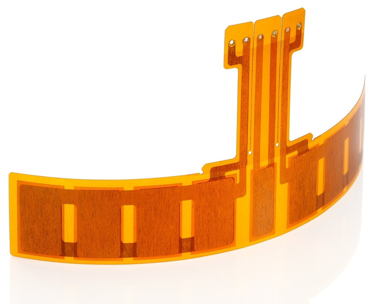
DuraAct patch transducers work both as sensors with variable bandwidth which react to mechanical deformation such as impacts, bending or pressure, and as high-precision controlling elements or bending actuators.
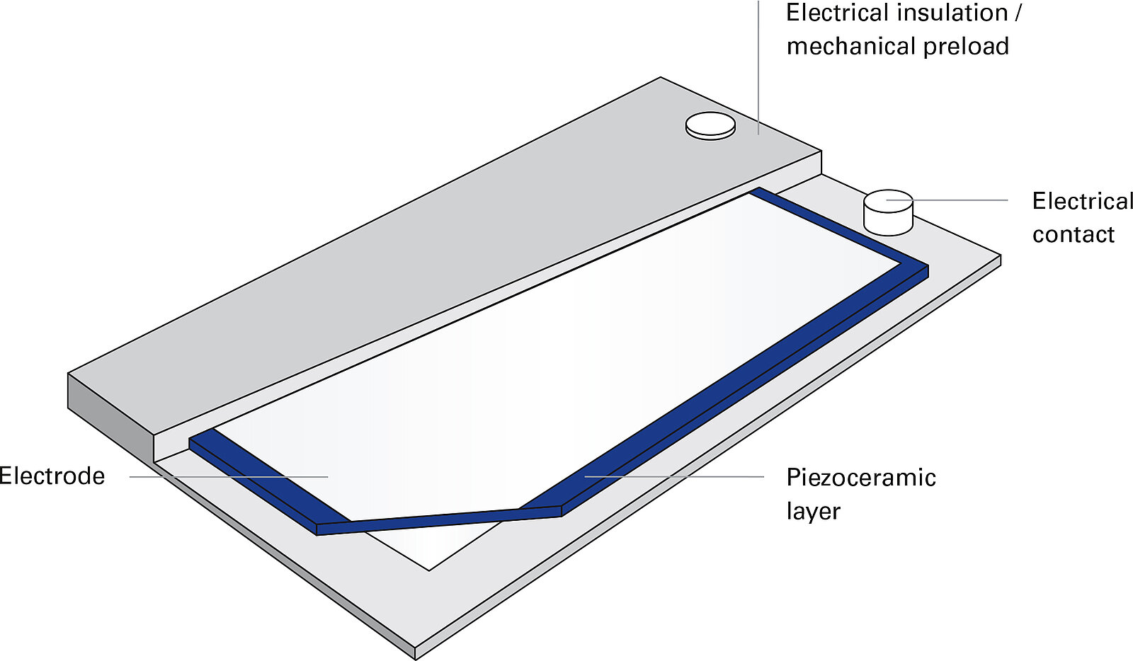
The active layer in DuraAct patch transducers consists of one or more piezoceramic plates with metallized surfaces for electrical contacting. These plates typically measure between 200 and 500 μm in thickness. They are embedded in fiber-reinforced plastic (GRP) using a patented process and bonded to form a composite. The bonding process is carried out in an autoclave in a vacuum by means of an injection process to produce completely bubble-free laminates of the highest quality.
The curing temperature profile of the autoclave is selected so that a defined mechanical preload of the piezoceramic plates will result due to the different thermal expansion coefficients of the materials involved. The polymer coating of the GRP also serves as electrical insulation. Robust, bendable transducer elements that can be manufactured in large batches are the result of this patented technology.
DuraAct patch transducers are solid body actuators without moving parts. This means that wear and failure proneness are minimal. The electrical connection is made via two contact points to which wires can be soldered, glued or clamped, depending on the application.
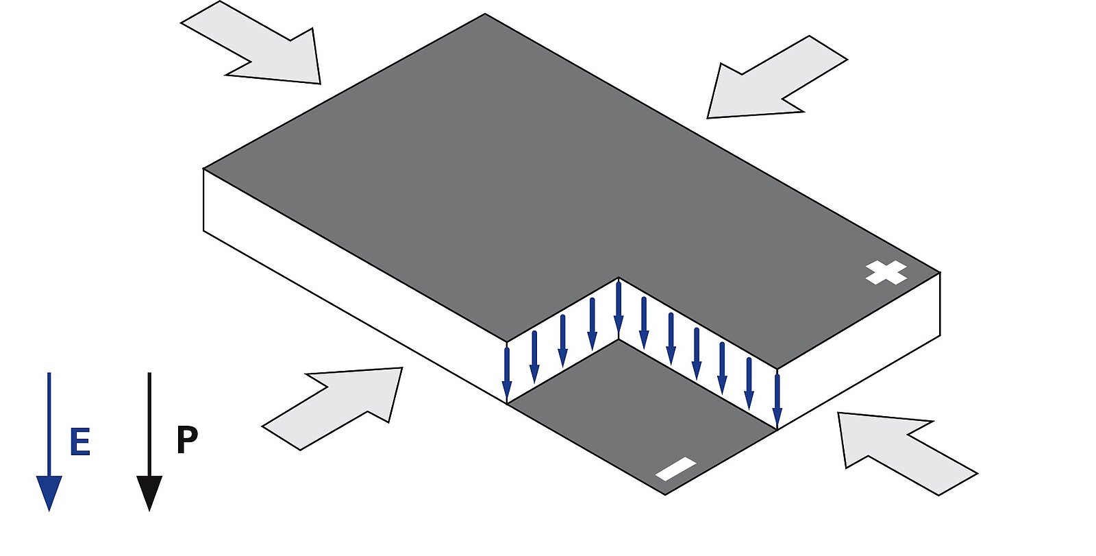
The piezoceramic plates that are used in all-ceramic DuraAct patch transducers are structurally similar to a capacitor. The ceramic serves as a dielectric between the metallic surfaces of the ceramic, which form the electrodes. When an electric voltage is applied, an electric field is created with lines running through the ceramic perpendicular to the plates. This causes a staggered contraction of the ceramic at 90° to the field lines so that the actuator constricts evenly along the plane. This behavior is called the transverse piezoelectric (d31) effect.
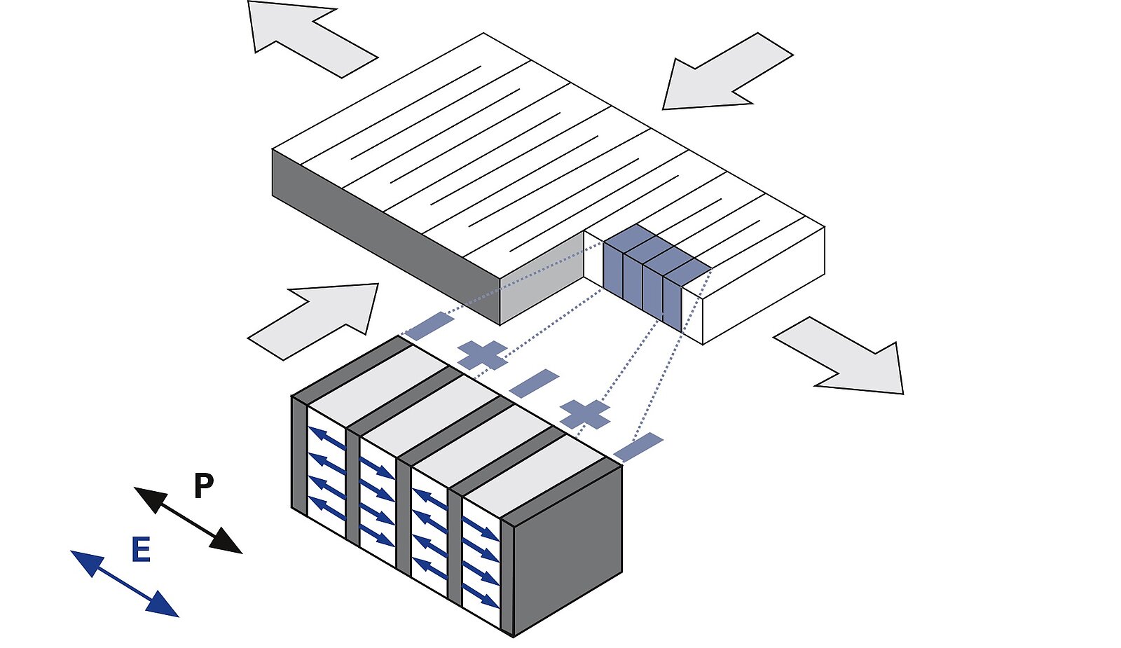
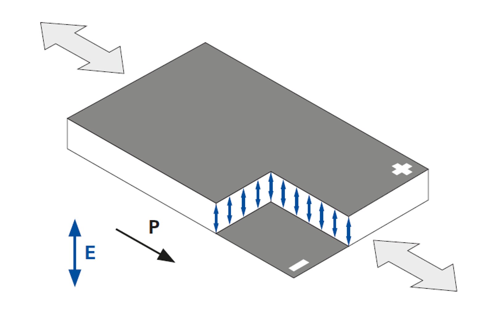
In the DuraAct Power patch transducer the multi-layer piezo element draws on the longitudinal or d33 effect. The displacement occurs parallel to the electric field E and the polarization direction P of the piezo actuator. The piezoelectric charge coefficients d33 for the longitudinal displacement are considerably higher than for the transversal displacement, meaning that the possible displacements are greater than for all-ceramic transducers.
The occurrence of acoustic surface waves can be converted using DuraAct Shear patch transducers. The shearing motion of the patch transducer is produced by the orthogonal application of an electric field E to the direction of the polarization P. The shear deformation coefficients d15 are generally the largest of the piezoelectric coefficients. When controlled with nominal voltages, the piezo ceramics achieve d15 (GS) values of up to 2000 pm/V. The permissible control field strength is limited in order to prevent a reversal of the vertically oriented polarization.
The electric field strength of the DuraAct patch transducers determines the displacement of the ceramic, therefore, allowing the simple control of the modules. This deformation is transmitted effectively to the structural elements via an uncomplicated bonding. The force is transmitted across the entire surface of the actuator by thrust and not at discrete points as is the case with conventional actuators. Massive force transfer points are therefore unnecessary. Conversely, structural deformations are converted to an electrical charge by the transducer, making it possible to use the element as a sensor or power generator. Division of the sensor and actuator functionality is achieved using an isolated contacting of several layers.
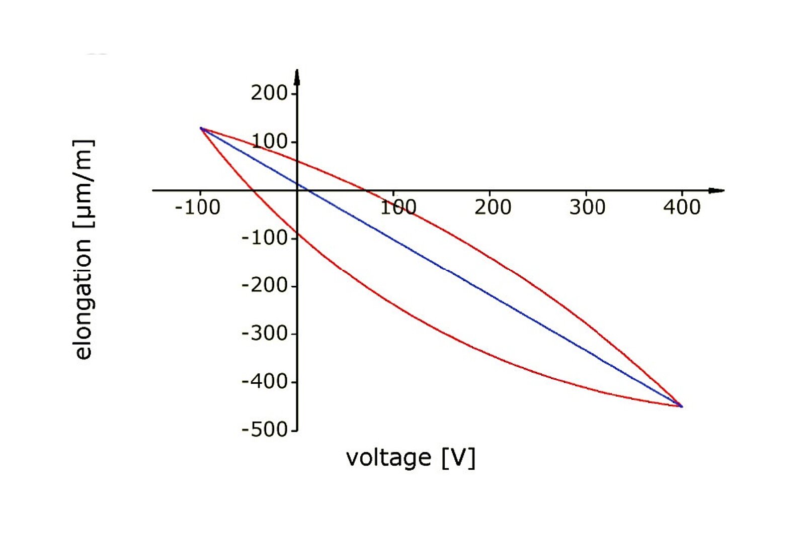
The reaction to a change in the electrical field or a deformation is extremely fast. This allows oscillations to be generated into the kilohertz range or also measured. Depending on the active piezo element used and its dimensions, different actuators produce different values with respect to control voltage and contraction. The relationship between deformation and control voltage is not linear.
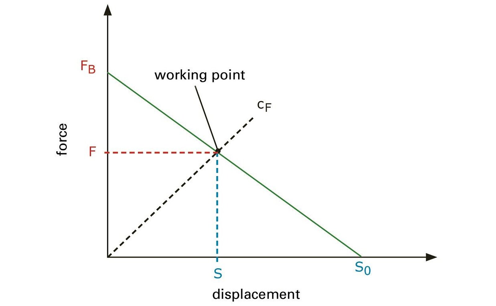
The actuator characteristics of piezoceramic transducers are primarily described by means of two parameters: the blocking force FB and the free displacement S0. If the unimpeded (free) actuator is controlled with a voltage U, it reaches its maximum displacement S0. The force required to push the maximally displaced actuator back to its original length is called the blocking force FBI.
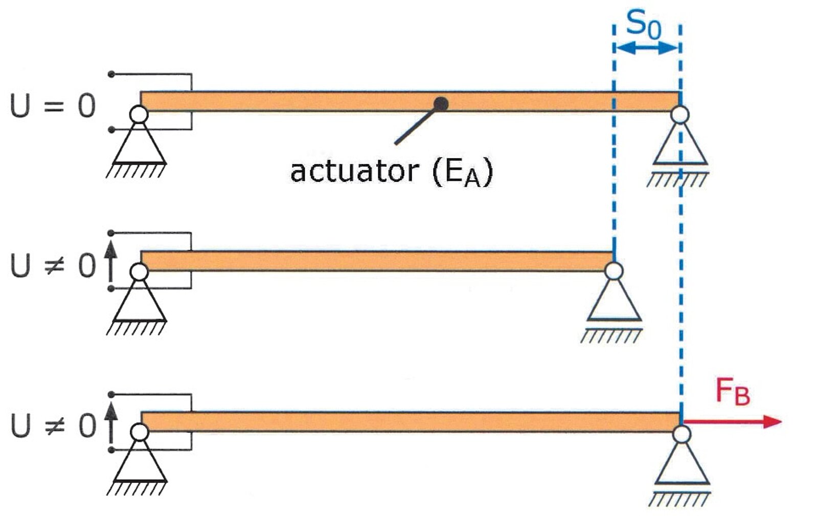
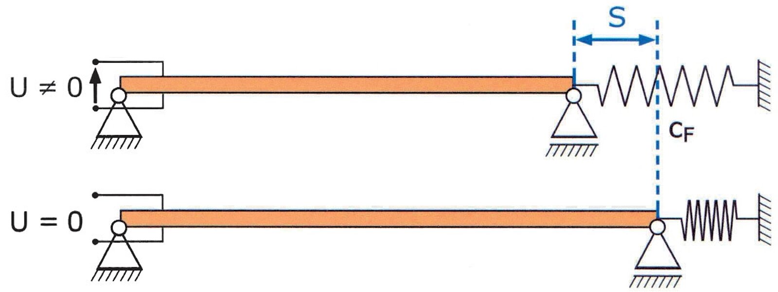
If both parameters are plotted on a graph and connected with a line, the result is the performance graph of the actuator. The connecting line is called the load line. The ratio of external force to displacement can be read from the graph. In most applications, the actuator works against an elastic structure such as when deforming a spring or bending a plate. If the actuator deforms a spring, for example, the characteristic curve of the spring is plotted on the performance graph with the stiffness cF. The intersection point of the load lines and the characteristic curve denotes the operating point. The actuator works most effectively when the operating point is in the middle of the load lines.
Bending Actuator – Parameters
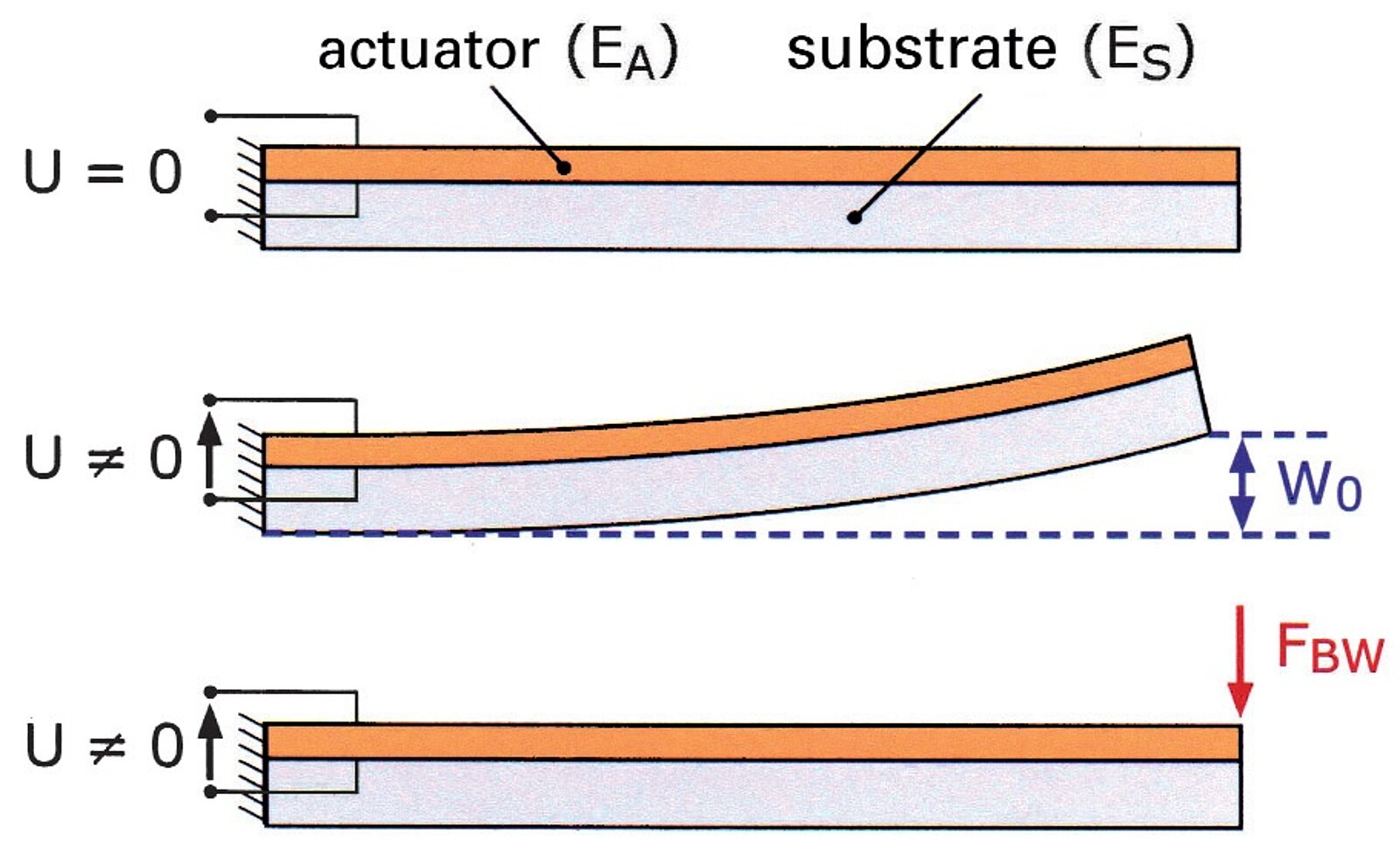
Actuators from the DuraAct product group are generally glued to a structure and do not transfer the strain at specific points, but rather across the whole adhesive layer. In a configuration like this, the actuator works as a bending actuator. Bending actuators are used for many engineering applications which require quick, precise and reproducible stroke movements, for example in textile machines, printers or valves.
As DuraAct patch transducers are based on the transverse piezoelectric effect, they contract evenly when an electric field is applied. This causes the bending actuator to bend. The bending of the unimpeded, free bending actuator is termed as free displacement W0. The force required to reduce the free displacement to zero is the blocking force FBW of the free transducer. This force FBW is considerably less than the blocking force FB of the free transducer. As with the previously described correlations, the performance diagram of the bending actuator can be plotted using these two parameters.
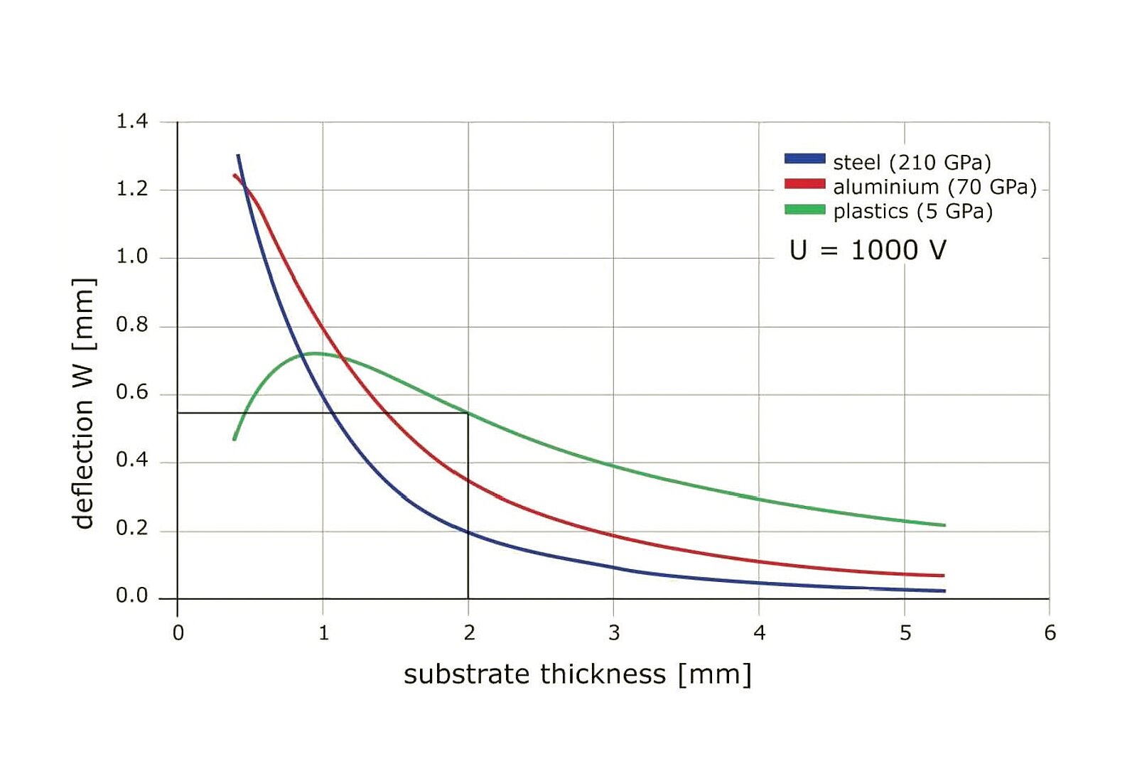
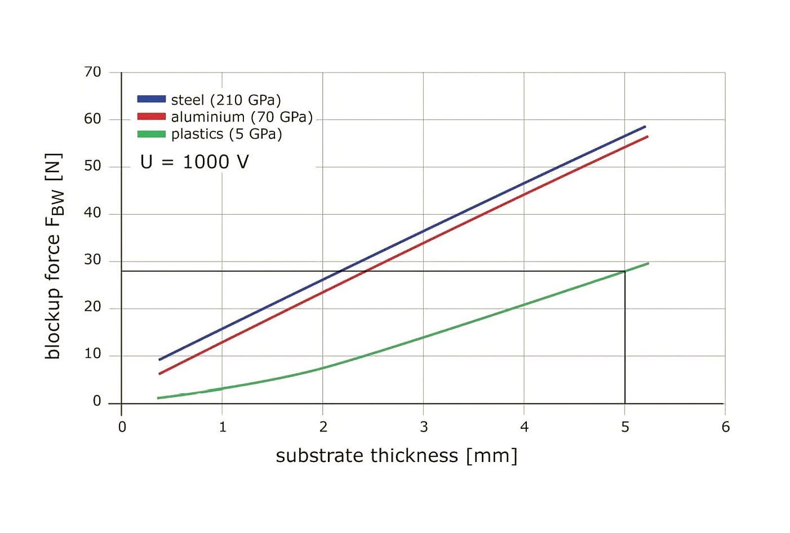
To evaluate the free strain W0 and the blocking force FBW, charts can be used which show, for example, the achievable displacements and forces as a function of the thickness and stiffness of the substrate used. The two graphs are plotted based on two substrates with a length of 50 mm made from different materials to which a DuraAct type P-876.A15 patch transducer is mounted. Together with the performance graph, the bending actuator graphs provide an effective basis for evaluating the performance and behavior of an actuator for a specific application. For this reason, they are provided on every datasheet.
DuraAct Patch Transducer Power Requirements
To estimate the electrical requirements necessary for the operation of an actuator, the capacitance of the transducer plays an important role. The capacitance values of DuraAct patch transducers are typically in the nanofarad range and in each case are provided on the datasheets.
Here, the capacitance C is dependent on the type, thickness and area of the piezo ceramic used. To estimate the average electrical output Pm, the control frequency as well as the capacitance of the transducer and the voltage swing are required.
Pm = C · f · Uh2
f: frequency, Uh: voltage swing
The maximum power requirement Pmax can be calculated by multiplying the average electrical output by pi (π):
Pmax = Pm ・ π